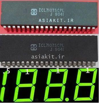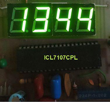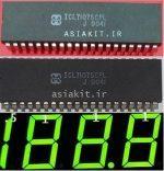
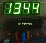
مبدل آنالوگ_دیجیتال ۳.۵ رقمی مخصوص ۷سگمنت ICL7107CPL
55,000 تومان
ساخت ولتمتر،آمپرمتر،اهمتر،دما سنج،ترازو،لودسل و…
دقیق با آی سی ICL7107CPL
فوقالعاده دقیق با آی سی ICL7107SCPL
برای قیمت ICL7107SCPL تماس بگیرید
ORIGINAL IC. کاتالوگ: PDF
ناموجود
مبدل آنالوگ_دیجیتال 3.5 رقمی
مبدل آنالوگ_دیجیتال 3.5 رقمی آی سی ICL7107CPL.یک مبدل آنالوگ به دیجیتال 3.5 رقمی است که ورودی آنالوگ را به صورت دیجیتال. بر روی سون سگمنت های LED یا LCD نشان داده می شوند.از خصوصیات این آی سی.خواندن صفر برای ورودی صفر ولت در همه رنجها و نیز پلاریته صحیح در صفر برای تشخیص نول واقعی می باشد.این قطعه برای نمایش اعداد ولتمتر مناسب می باشد. هسته این آی سی از یک مبدل آنالوگ به دیجیتال ، یک پردازنده کم مصرف ولی پر سرعت ، دیکدر نمایشگر هفت قسمتی ، درایور نمایشگر ، ولتاژ رفرنس و تولید کنند کلاک ساعت تشکیل شده است . در واقع تمامی تجهیزات مورد نیاز برای نمایش دقیق ولتاژ روی 7Segment را در درون خود دارد.
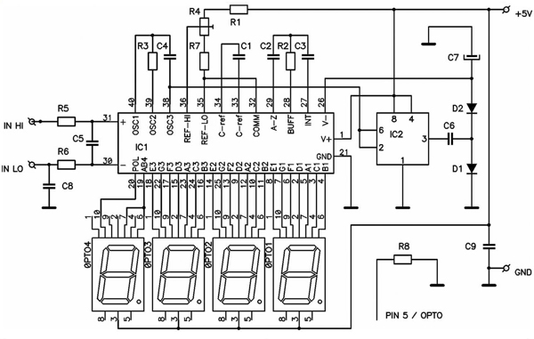
ساخت ولتمتر با مبدل آنالوگ_دیجیتال 3.5 رقمی

ولتمتر
لیست قطعات :
- مقاومت R1=180K اهم
- مقاومت R2=22K اهم
- مقاومت R3=1.2K اهم
- مقاومت R4=1M اهم
- مقاومت R5=470K اهم
- مقاومت R6=560Ω اهم
- پتانسیومتر(مولتی ترن) P1=20K اهم
- خازن عدسی C1=100pF
- خازن عدسی C2=100nF
- خازن عدسی C3=47nF
- خازن عدسی C4=10nF
- خازن عدسی C5=220nF
- ای سی U1=ICL7107 به همراه سوکت
- 4 عدد سون سگمنت اند مشترک
Features, Applications |
|
The Intersil ICL7106 and ICL7107 are high performance, low power, 31/2 digit A/D converters. Included are seven segment decoders. display drivers, a reference, and a clock. The ICL7106 is designed to interface with a liquid crystal display (LCD). and includes a multiplexed backplane drive. the ICL7107 will directly drive an instrument size light emitting diode (LED) display. The ICL7106 and ICL7107 bring together a combination of high accuracy, versatility. and true economy. It features autozero to less than 10µV. zero drift of less than 1µV/oC, input bias current of 10pA (Max).and rollover error of less than one count. True differential inputs and reference are useful in all systems. but give the designer an uncommon advantage when measuring load cells, strain gauges and other bridge type transducers. Finally, the true economy of single power supply operation (ICL7106). enables a high performance panel meter to be built with the addition of only 10 passive components and a display. Features.Guaranteed Zero Reading for 0V Input on All Scales True Polarity at Zero for Precise Null Detection 1pA Typical Input Current True Differential Input and Reference, Direct Display Drive – LCD ICL7106, LED lCL7107 Low Noise – Less Than 15µVP-P On Chip Clock. and Reference Low Power Dissipation. Typically Less Than 10mW No Additional Active Circuits Required Enhanced Display StabilityPART NO. ICL7107SCPL ICL7107CM44 TEMP. RANGE (oC) to 70 PACKAGE 40 Ld PDIP 44 Ld MQFP 40 Ld PDIP 40 Ld PDIP (Note) 40 Ld PDIP (Note) 44 Ld MQFP PKG. NO. E40.6 Q44.10×10NOTE: “R” indicates device with reversed leads for mounting to PC board underside. “S” indicates enhanced stabilityCAUTION: These devices are sensitive to electrostatic discharge; follow proper IC Handling Procedures. 321-724-7143 | Intersil (and design) is a registered trademark of Intersil Americas Inc. Copyright © Intersil Americas Inc. 2002. All Rights Reserved(1000) AB4 (MINUS) POL OSC 1 39 OSC 2 38 OSC 3 37 TEST 36 REF HI 35 REF LO 34 CREF+ 33 CREF32 COMMON LO 29 A-Z 28 BUFF 27 INT G3 21 BP/GND (100’s) OSC 1 OSC 2 OSC 3 TEST REF HI REF LO CREF+ CREFCOMMON IN LO A-Z BUFF INT A3 G3 BP/GNDSupply Voltage V- to GND. -9V Analog Input Voltage (Either Input) (Note V+ to VReference Input Voltage (Either Input). V+ to VClock Input ICL7106. TEST V+ ICL7107. GND to V+Thermal Resistance (Typical, Note 2) JA (oC/W) PDIP Package. 50 MQFP Package. 75 Maximum Junction Temperature.150oC Maximum Storage Temperature Range. to 150oC Maximum Lead Temperature (Soldering 10s).300oC (MQFP – Lead Tips Only)CAUTION: Stresses above those listed in “Absolute Maximum Ratings” may cause permanent damage to the device. This is a stress only rating and operation of the device at these or any other conditions above those indicated in the operational sections of this specification is not implied.NOTES: 1. Input voltages may exceed the supply voltages provided the input current is limited JA is measured with the component mounted on a low effective thermal conductivity test board in free air. See Tech Brief TB379 for details. Electrical Specifications PARAMETER SYSTEM PERFORMANCE Zero Input Reading Stability (Last Digit) (ICL7106S, ICL7107S Only) Ratiometric Reading Rollover Error VIN = 0.0V, Full Scale = 200mV Fixed Input Voltage (Note 6) VlN = VREF , VREF = 100mV -VIN = +VlN 200mV Difference in Reading for Equal Positive and Negative Inputs Near Full Scale Full Scale 200mV or Full Scale = 2V Maximum Deviation from Best Straight Line Fit (Note 5) VCM = 1V, VIN = 0V, Full Scale = 200mV (Note 5) VIN = 0V, Full Scale = 200mV (Peak-To-Peak Value Not Exceeded 95% of Time) VlN = 0 (Note 5) VlN To 70oC (Note 5) VIN To 70oC, (Ext. Ref. 0ppm/× oC) (Note 5) VIN = 0 (Does Not Include LED Current for ICL7107) Digital Reading Digital Reading Digital Reading Counts (Note 3) TEST CONDITIONS MIN TYP MAX UNITLinearity Common Mode Rejection Ratio Noise Leakage Current Input Zero Reading Drift Scale Factor Temperature Coefficient End Power Supply Character V+ Supply CurrentEnd Power Supply Character V- Supply Current ICL7107 Only COMMON Pin Analog Common Voltage Temperature Coefficient of Analog Common DISPLAY DRIVER ICL7106 ONLY Peak-To-Peak Segment Drive Voltage Peak-To-Peak Backplane Drive Voltage = 9V (Note 4) 25k Between Common and Positive Supply (With Respect to + Supply) 25k Between Common and Positive Supply (With Respect to + Supply) |
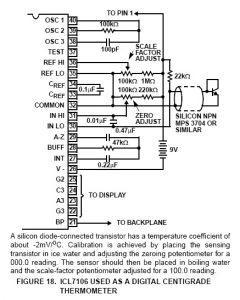
دماسنج
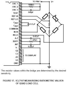
لودسل


